BITS FOR LINDY: THE SPARES OF XL190, 1999 SOURCING MORE SPARE PARTS FOR ANDRE AND VICTOR K2 XL231 “LUSTY LINDY”
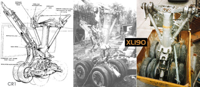
Above: Inset pics 1 & 2: XL190’s nose leg with original illustration. The nose unit was secured for Andre, the towing arm being removed later and scrapped. The single retraction jack can be seen bottom left Inset 3: With Andre after the 3rd breakdown and passing on other Victor items for Lindy.
Despite reports in the aviation press to the contrary nobody from Elvington managed to get down to the final St Mawgan resting place of XL190, as has been confirmed by Andre Tempest some time ago. The V.A. was subsequently charged at Andre’s request to obtain whatever we could to ensure that as many useable items were saved before the airframe was scrapped.
Over a 6 week period therefore I travelled to an Essex scrapyard to reserve and oversee any items on Andre’s behalf as they arrived, in lieu of many main components being disposed of locally at St Mawgan itself. A typed wants list was compiled before the scrapping began in January 1999 by Andre and faxed to my office, which ran something like this:
1. Nosewheel leg as complete as possible with steering jacks attached.
2. AAPP (APU) Starter Motor: Situated on bottom of Artouste engine STB’D WING ROOT.(A simple job to remove apparently, just 2 electrical connections and its held on by x 1 jubilee clip).
3. Any loose fuel pumps or float units which might have been removed for fuel tank purging.
4. ANY black boxes from anywhere in the a/c, mainly in & around the nose section including plenum chamber. If time could not allow proper removal and it was possible to cut any sections out with them in situ, then this was specified – this was ultimately not possible unless any interested parties could do it themselves, as the dealer concerned had time constraints and the weather, as expected, was bitterly cold!
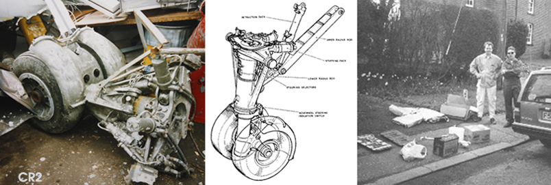
4.x 2 main undercarriages for spares use with wheels, if not complete legs at least bottom bogies with wheels on.(We had seen the MOD report on these and knew the u/c’s were badly corroded with two wheels shattered and tyres burst, but any existing components that were useable might help out Lindy in the future).
5. Any circuit breakers and contactors.
6. x 1 Voltage Regulator in Plenum Chamber. Part No AE7306. LOCATION: Facing aft top rack on right- about 6 electrical connections (for AAPP main electrical reg).
7. Fuel amplifier units ALL located under access lip to Plenum Chamber, racked vertically. (Apparently x 1 electrical plug and x 1 Dzeus clip to attach it to the aircraft).

Above: Inset Pic 1: Main UC leg illustration; Inset Pics 2 & 3: Both main u/c legs of XL190 in ‘the yard’. I had asked that both main legs be retained for Andre along with the nose leg, but one of the main legs was removed weeks before Andre’s arrival. They were especially needed for the wheel brake pads, but fortunately Andre later traced the removed item to Duxford I believe, where the brake items were removed by him with the owner’s blessing as they were internal and would not be missed on the displayed item.
LOCATION FOR STARTER MOTOR FOR APU :
There is a bulge under STB’D wing only which runs forward to aft. This is inboard of the engines, below the main intakes. If air scoop is open it faces you when looking from the front. There are 2 curved doors which join length-wise, with an exhaust duct at the rear of the bulge. With doors open, the starter itself is pretty much like a car one, black coloured with the 2 electrical (dirty orange) cables going into the back. Its pinion is like a star drive with a shaft a couple of inches long – it may have ‘Plessey’ on it, as they manufactured them.
AAPP FUNCTION
The AAPP, installed in the starboard wing stub provides low pressure air for starting the main engines. The unit also provides electrical power for maintenance or servicing purposes on the ground when a ground supply is not available or for essential services in the air should the main generating system fail.
HOBSON PFCU
231’s aileron powered control unit went U/S at this time, and one of 190’s would obviously have been a help. It can be found in front of the ailerons where a stress panel with around 60 screws on it marks the location for the unit. Time again was at a premium, but although Lindy is OK now it would still be an obvious help to have a replacement unit(s) for the future. If anyone knows of any then please contact Andre at Elvington.
ALIGHTING GEAR : GENERAL
The nose and main units of the alighting gear are actuated by a single jack each. Internal jack locks secure the units at the retracted positions and the nose unit at its extended position. The main units are locked down by external spring-loaded-to-engage-hooks. The associated wheel bay doors are operated by auxiliary jacks, the correct operating sequence being controlled by mechanically operated sequence valves.
THE BEST LAID PLANS…
After being assured by my then-girlfriend that her Volvo was A1, I took the other smaller items saved for Andre with me to meet him at the yard on 13 March – and promptly broke down 3 times with electrical problems – (I don’t go out with her anymore). Andre had to drive from the yard and met me at Margaretting Village Hall Essex, and after a sherbert and handing over things over with the V.A.’s compliments we bid each other farewell while I waited for the AA. Oh well, at least I found a lovely pub that did a special Cod and Chips in their own beer batter.

Above: Inset Pic 1: The Conway engines lie idle at the yard after removal from XL190. Their long job done, they await removal and breaking down for scrap; Inset Pic 2: I can’t recall if this was XL190’s original radome or a spare, but it was at the yard and thereafter I have no recall. Inset Pic 3: Many plenum chamber louvre doors and airframe/wing plugs and bungs were also recovered by the Victor Association and passed on to Andre for ‘Lindy. Many of them were marked up with the old-style red pennants with a ‘Victor B.2’ designation.

